How to Use
To apply fibre-optics in the field, experience with splicing (i.e. precise welding of fibre-optics to connectors) is crucial. Knowledge of computer systems and the DTS system is practical. The data from the DTS-system can be analysed using Matlab.
- Phased Plan Process
- Installation of a fibre-optic DTS system
- Advice and recommendations
1. Phased plan process
2. Installation of a Fibre-optic DTS System
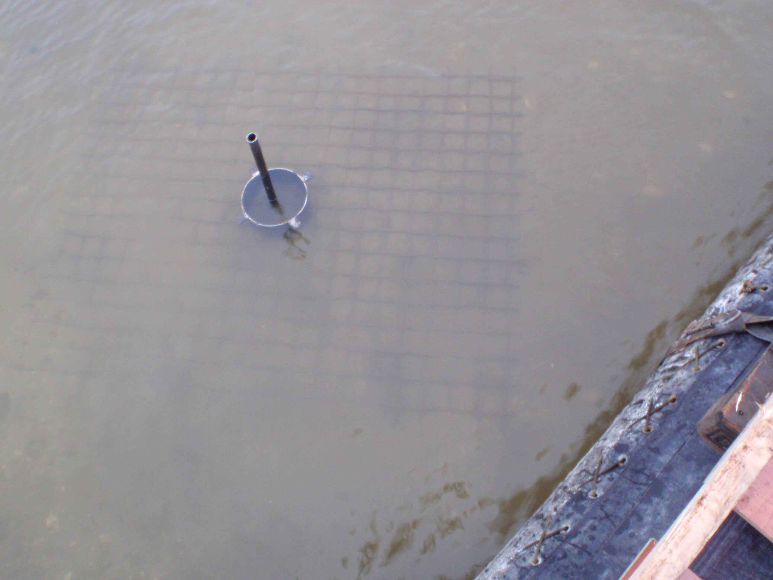
The fibre-optical cables have to be placed in the field, preferably in an easy-to-demobilize setup. Depending on the required information, one could choose between a horizontal grid to measure lateral displacements, or coiled fibre-optical cables around a vertical pole to measure changes in height, or a combination of the two. Coiling increases the resolution of the measurements because more cable length is wrapped over a short distance around a pole. In the case of a horizontal grid, the cable should be dug in or placed before any sediment body is placed on top of it. In the case of a vertical pole, pole and cable should be dug partly into the ground.
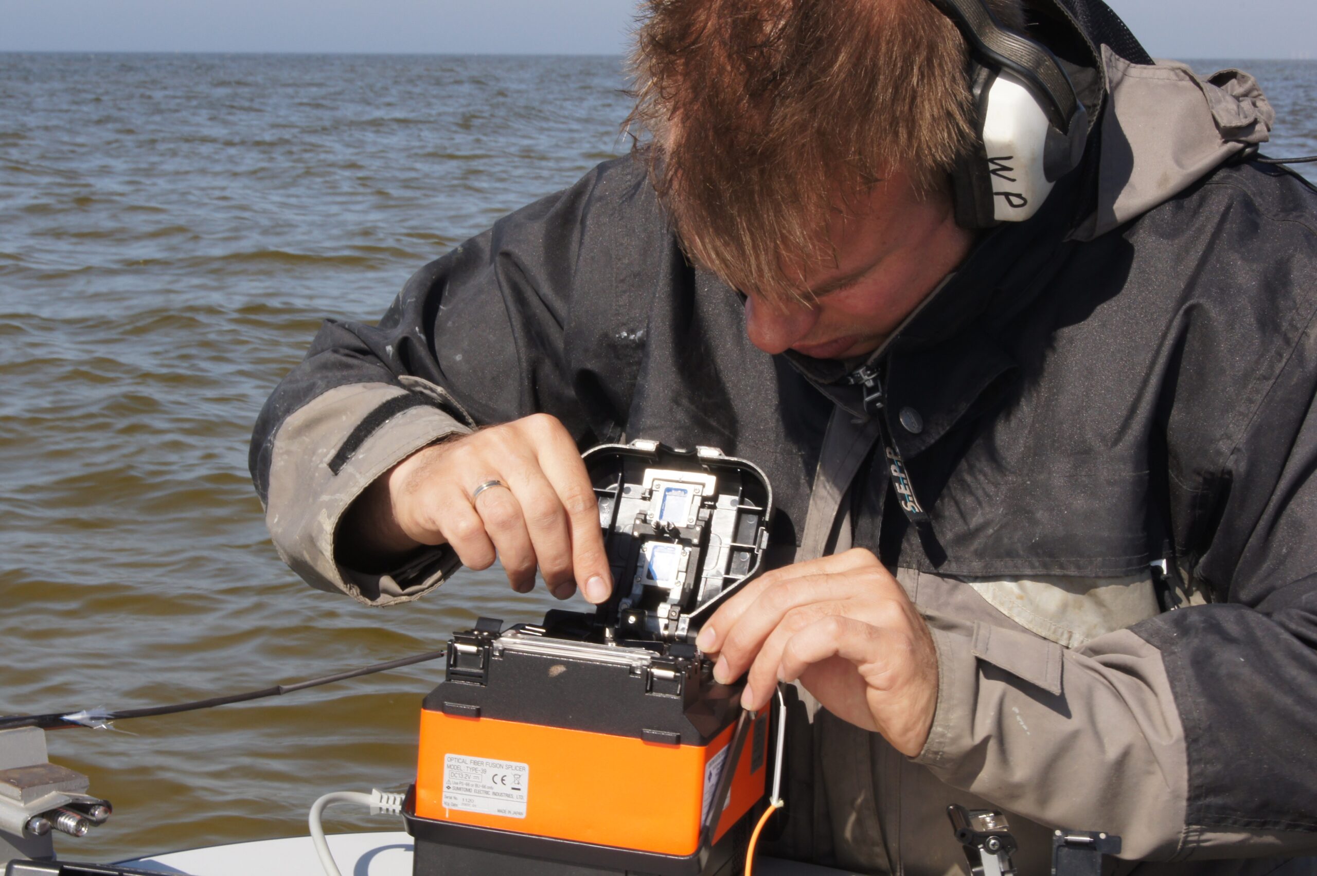
The exact position of the cable should be known in order to properly map the measured erosion and sedimentation. The exact position can be accurately determined in the field with a (Differential Global Positioning System) DGPS and distance indicators (numbers) that are printed on the cable (every meter). The end of a cable has to be spliced (precise welding of fibre-optical cables) to a connector, which connects the cable to the DTS system. This system can be made stand-alone and installed on a platform (containing a battery pack, solar panels and telemetry).
Types of fibre-optic cables
Many types of fibre-optical cables are commercially available, and innovation in this field develops quickly. In the case Sand engines – IJsselmeer (NL) a black reinforced cable of 1 cm thick was chosen, but thinner cables more suitable for coiling are also available. Lately, cables have been introduced that can be heated from the inside by applying an electrical current. These cables enable the monitoring of erosion and sedimentation in areas with minor day-to-day temperature variations, such as deeper seas. In this case the dissipation of the heat generated by the cable is a function of the sediment thickness.
The following software is needed for processing the data:
- Programming software (e.g. Matlab or Java, C++) to write scripts that derive the position and thickness of the sediment layer above the cable from the temperature data. These scripts have to be customized for every situation, for instance depending on experimental setup, sediment properties and temperature variability.
- Visualisation software (Matlab, ArcGiS, OpenEarth) to visualise morphological changes
3. Advice and recommendations
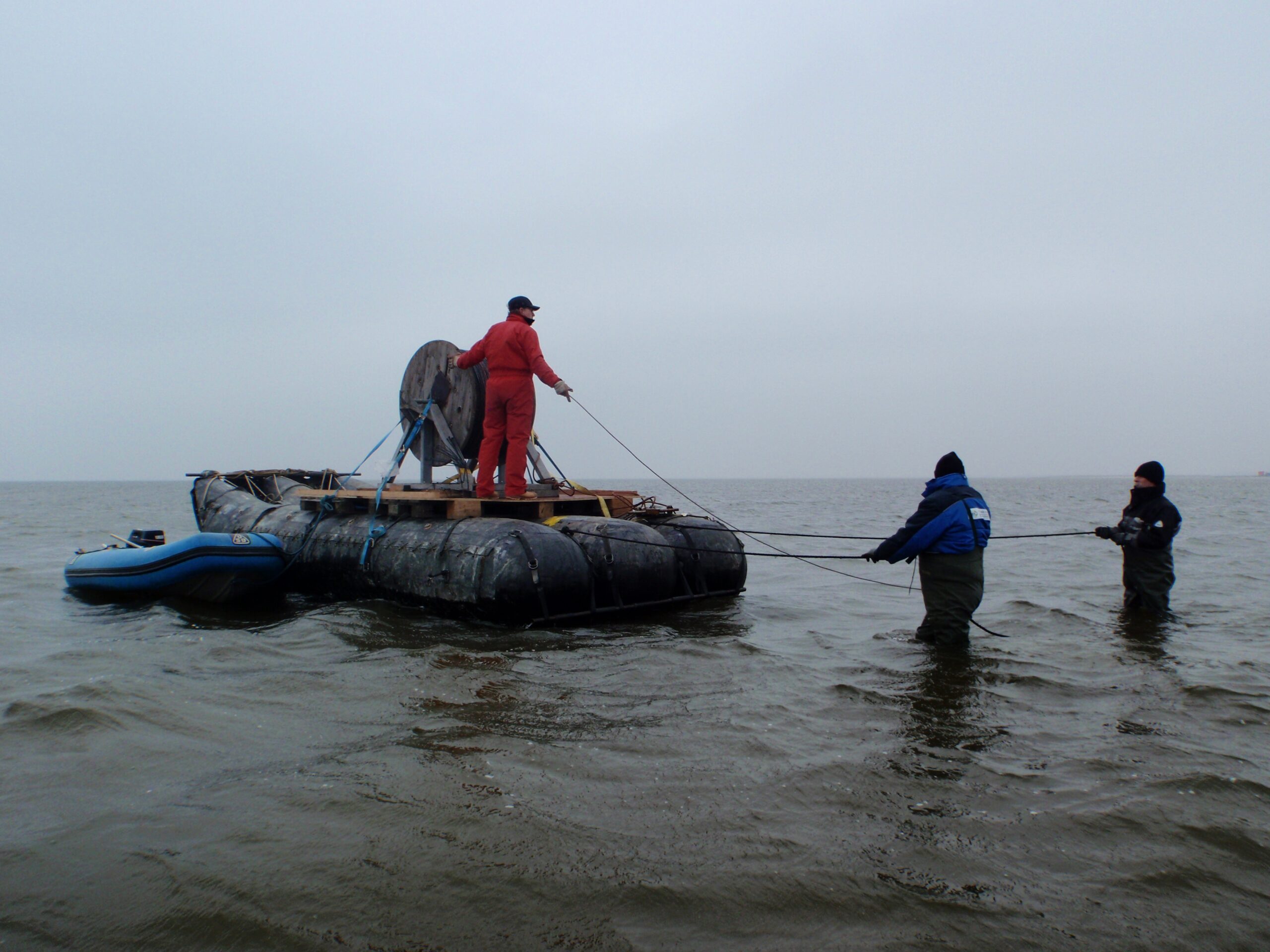
For the Sand engines – IJsselmeer (NL) the cable had to be placed in shallow water (< 1m). A rubber raft was used to hold the cable-winch and roll out the cable. As corner points, Ribbed steel welding nets were used with a flange welded on top of it. These nets were kept in place by steel pegs.
- The cable was held down by steel pegs which held the cables from moving.
- Make sure the position of the grid is well indicated so no boats can damage the fibre-optical cables.