Initiation
Building with Nature was asked to initiate experiments on innovative solutions for the coast and to ease relations between parties with different interests.
Pre-feasibility
During the pre-feasibility study several workshops and meetings were held with different (governmental) parties involved, in order to affirm interests, to gain a clear picture of the experiments and to reach a statement of intent regarding the lake area. In this phase, negotiations were facilitated by a movie with decision makers expressing the importance of a building with nature approach for Fryslan. This movie showed support and provided informal legitimization from high-ranking authorities for the experiments. It was no longer questioned whether the project would be carried out, discussions rather shifted to how it would optimally succeed.
Feasibility
In the feasibility phase two studies were conducted: pre-conditions of eco dynamic design (Building with Nature, 2011) and an ecological assessment (Deodatus & de Jong, 2010)
Planning and design
The Workumerwaard is the first of three experimental sites where a sand engine was to be tested. One of these (Hindeloopen) has been cancelled after stakeholder protests, the other has recently (2013) been implemented.
A soft sand engine in the Workumerwaard
The Workumerwaard nourishment started in June 2011 and was completed in October of that year. The overarching goal of the project was to revitalize nature by turning coastal erosion into gradual accretion. At first sight, the process seems fairly simple: deposit an amount of sand on the shore face and let waves and currents bring it onshore. Yet, the actual creation of a sand engine in front the Workumerwaard turned out to be a complex process. It Fryske Gea (2011) has reported many of the steps taken in detail. The present page describes the most important aspects, from location selection to monitoring and evaluation.
Location selection
The pilot Workumerwaard consists of a concentrated shore face nourishment in the form of an elongated sand ridge combined with a pole screen perpendicular to the coast meant to trap the sediment at the right place. If the ridge is properly located, waves and currents will be able to gradually transport sediment onshore. Since Workumerwaard coastal system already includes a sandy shore and a wide floodplain with valuable wetland vegetation in front of a dike, this pilot aims at enhancing the robustness of nature, and thereby indirectly improving flood safety. Location is key in making the sand engine function as intended. Some important characteristics that need to be taken into account are:
- Sediment dynamics.
- Nature values and hydrological impact on water vegetation.
- Use of the area and municipal borders.
Sediment dynamics
Even after the Afsluitdijk dam was built, the lake bed has remained dynamic (see the knowledge page on sediment and ecology). Wind-induced waves and currents are strong enough to move sediment around. Due to differences in local characteristics like depth and average wind speeds, large variations in sediment transport capacity occur along the Frisian IJsselmeer coast. Several hydrodynamic and sediment transport models have been used in order to identify the best location for an effective sand engine.
In wave-induced sediment transport modelling a distinction is made between long shore and cross-shore current and transport components. The CROSMOR model has been used to describe them in a series of cross-shore transects. Below we describe how the model functions and what results have been accomplished. The following paragraph gives an overview of the sand dynamics model based on a comprehensive overview by Folmer et al. (2010).
The CROSMOR model is a “wave-by-wave” model where the wave equation is solved for each wave separate. In this model the following parameters have been varied:
- Cross shore profile
- Sediment size
- Water level
- Wave conditions
To gain a good overview of the pilot area, the model has been used in eleven cross-shore transects evenly distributed along the coast. With the mean grain size set at 200 μm and water levels between NAP -0,4 m en NAP +0,4 m, long shore and cross-shore sediment transport rates have been modeled. Transport rates for different water levels have been multiplied by the probability of occurrence of these water levels (Figure 1), in order to gain insight into where the sediment will go.The figure below shows the probability density function at measuring station Lemmer, based on 1988-2009 MWTL data (Monitoring Waterstaatkundige Toestand des Lands, a National Surface Water Monitoring Program) (Folmer et al. 2010).
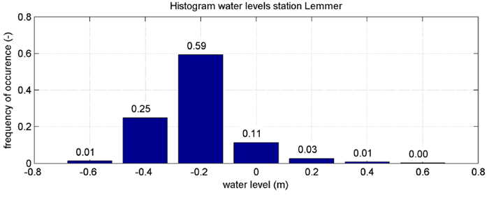
The yearly sediment transport in the area is the integral of this product over all water levels. Water levels are not exclusively correlated to wind and waves, because the water level regime differs between winter (relatively low, whereas wind speeds are generally higher) and summer (higher water levels, less wind). The computed sediment transport is shown in the picture in one of the eleven transects (top), for different water levels (middle) and integrated over the year (bottom). At higher water levels, sediment transport increases towards shallower water. At the same time, shore ward transport increases. As conditions favoring onshore transport are not very frequent, offshore transport at water depths of NAP -2 m to -1 m is the most frequent (Folmer et al. 2010).
This has been repeated for every selected cross section in the pilot area. The findings are visualized in the figure above, for the Frisian IJsselmeer coast. The arrows indicate the sediment transport direction, the thickness of the arrow the transport capacity. The biggest arrow represents the transport of about 1000 m3 pure sediment per year.
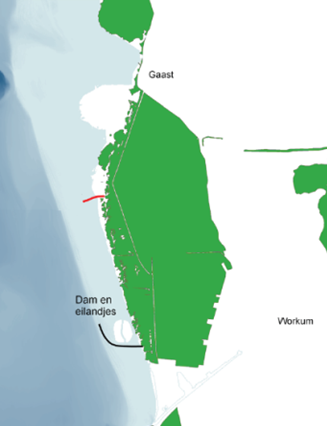
The CROSMOR results have been used to select a location for the soft sand engine somewhere between the harbour of Workum and Gaast. For this stretch of coast a detailed design of the pilot has been made. Within this area waves and wind conditions, as well as water depths, vary greatly. On the southern part of the Workumerwaard coast a low breakwater and a number of shoals determines to a large extent the wave dynamics. Further north wave activity increases and reaches a maximum in the northernmost part of the area. Generally speaking: the greater the wave energy, the larger the sediment dynamics. On the other hand, water depths in the north are relatively small, also further offshore. These shallow parts reduce the wave energy, hence the sediment transport capacity. Yet, from a sediment transport perspective, the optimal location for the nourishment is as far north as possible in not too shallow water. Since the sediment transport alongshore is much larger than cross-shore, the sand needs to be deposited south of the location where it is meant to feed the coast and where the pole screen is placed to trap it.
The breakwater and the shoals in the south are reducing local sediment dynamics. In the northernmost part of the area the lake is too shallow, which also limits sediment transport. The red line indicates the most suitable location for the pole screen (Folmer et al. 2010).
Apart from the location, the height of the sand ridge to be deposited and the length of the pole screen are very important. Again the CROSMOR model has been used, this time to investigate the relation between depth and sediment transport. Model runs have shown sediment transport to be biggest at depths between 1 and 2 m. Wave energy – even during storms – is too low to activate sediment transport in deeper parts of the lake. At depths less than 1 m the waves will break on the lake side of the sandbank, with offshore sediment transport as a possible consequence. The optimal location for a sand ridge creating onshore transport (Folmer et al. 2010). Based on CROSMOR model runs a location has been selected where – from a sediment perspective – a sand ridge of 25,000 m3 could best be built.
Nature values and hydrological impact on aquatic vegetation
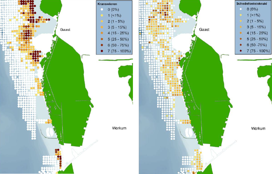
The CROSMOR model only takes sediment dynamics into consideration. The sand engine, however, will also change the other dynamics of the region and can have far-reaching consequences for existing aquatic vegetation. Impacts on nature need to be investigated, especially because the area is part of the European ecological network Natura2000. Based on aquatic plants monitoring program of Rijkswaterstaat, the potential impacts on submerged vegetation have been examined. The next paragraphs give an overview of the impacts on two types of submerged aquatic vegetation: Charales species and Stuckenia pectinata (It Fryske Gea 2011 and Folmer et al. 2010).
Charales species and Stuckenia pectinata
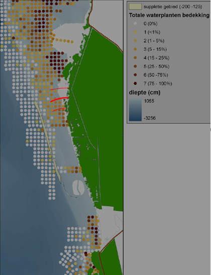
Alongside the Frisian IJsselmeer different types of pondweeds – or more specifically Charales – can be found: Chara aspera, C. connivens, C. contraria, C. globularis, C. hispida, C. virgata and C. vulgaris. Data provided by the Ministry of Infrastructure and the Environment do not distinguish between the different species of Charales and do not cover the area south of the central part of the Workumerwaard coast. The dispersal of Charales species in 2008: they are exclusively found in the most shallow parts near the shoreline. Depositing sand between NAP -2 and -1 m will therefore not have an impact on the Charales population. The largest patches of Stuckenia pectinata can be found at the northern part of the study area. From a sediment transport perspective this is not the best location for a soft sand engine.
The effects of the sand engine on submerged aquatic vegetation
As shown, a sand engine at the location and with the dimension described above will have a limited impact on the two most common species of submerged aquatic vegetation. Impacts of induced sediment deposition further onshore are expected to be minor, as well, since this deposition process will be gradual. The sediment-trapping pole screen will be located in a zone where both types of aquatic vegetation are present. The direct impact is expected to be limited if the poles are placed carefully. Besides, as both species are annual, populations are expected to recover quickly from any temporary disturbance.
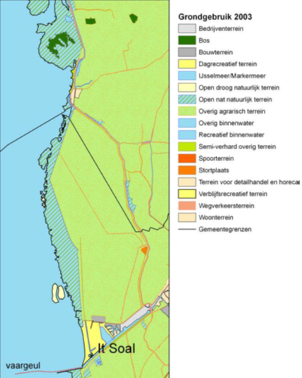
Land use in the Workumerwaard
Land use in and around the Workumerwaard is diverse. The westernmost part of the area is only protected by a small natural sand ridge. The open and wet nature here is characterized by shell banks and sand sheets and forms a natural transition from the waters of the IJsselmeer towards the mainland. From a hydrodynamic perspective this is the most suitable location for the sediment-catching pole screen. Further landward the area is used for low-intensity agriculture and plays an important role for resting and nesting godwits.
Recreational area It Soal, located south of the Workumerwaard, has sandy beaches with surfing opportunities. If the pole screen would be constructed south of this area, the sand engine should be placed even further south. This is not an attractive option, as the resulting sedimentation is likely to interfere with current land and water uses, in particular surfing activities.
Conclusion location selection
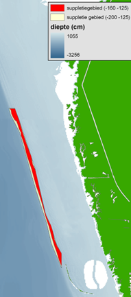
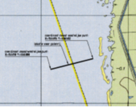
In conclusion, the northern part of the Workumerwaard is the most suitable for the pole screen, with the nourishment to the southwest. Impact on aquatic vegetation is expected to be minor and temporary and there is no interference with other forms of land use. The best locations for the nourishment are indicated with yellow lines and the pole screen (the thick red line marks the most suitable location, the thin red lines are other options).
Design of the soft sand engine
The soft sand engine consists of two parts, a concentrated shore face nourishment in the form of an elongated sand ridge and a sediment-trapping pole screen perpendicular to the coast.
Design of the sand bank
Once the location had been chosen, the final design of the soft sand engine was made. The budget available allowed for some 25.000 m3 of sand, which would be obtained from dredging projects near the recreational area of It Soal, south of the Workumerwaard. As this is a fairly small volume, the ambitious goals of the project of the three sand engines had to be adapted (It Fryske Gea 2011). Creating a sand engine in front of the Workumerwaard aims:
- To give insight into natural processes (wind and waves) as a mechanism to transport nourished sand onshore in a low-dynamic (as compared with an open coast) wind-driven environment.
- To gradually supply the coast of the Workumerwaard with additional sand, stimulated by a sediment-trapping pole screen. The resulting morphological changes should be such, that the existing vegetation is able to survive.
- To monitor the effects of this soft sand engine and learn from this experiment for other foreshore management projects in shallow delta lakes; as storms trigger sediment dynamics, monitoring should last long enough to have had enough storms to yield noticeable morphological changes (erosion and sedimentation).
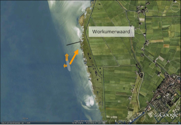
An impression of the soft sand engine near the Workumerwaard is shown in the figure below (It Fryske Gea, 2011). This figure shows the location of the soft sand engine pilot; arrows show the direction and magnitude of the sediment transport, the grey oval is the nourishment the black line represents the pole screen.
The characteristics of the nourishment are given in the table below.
| Characteristic | Description |
| Footprint | 500 x 100 |
| Crest level | NAP – 0.70 m |
| Shape | Elongated oval |
| Volume | 25.000 m3 |
| Grain size | 125-180 µm |
| Slope | Natural |
A cross-section of the nourishment shows that its crest will be at about 0.3 m below the target mean water level during winter time. This keeps the nourishment from surfacing under average conditions. Offshore winds, however, can force the water level to drop by 0.5 m, which would result in emergence of the crest. The biggest morphological changes are expected during south-westerly and north-westerly storms. Under these conditions, water is set up against the Frisian coast and may rise with more than 0.5 m and wave action is expected to induce extensive sediment dynamics, mainly onshore directed.
Design of the pole screen
The goal of the pole screen is to slow down long shore currents and stimulate sediment deposition in its vicinity. The degree of flow reduction must be determined carefully, as too much reduction may keep sediment away from the screen. In Bangladesh research on pole screens has shown that flow blockage should be between 30 and 70% (Government of Bangladesh, Ministry of Water Resources, 2001). In the Workumerwaard cage a blockage of about 50% is expected to give the best results.
Design criteria for the pole screen were therefore (It Fryske Gea, 2011):
- The pole screen should consist of untreated wooden poles (C14 quality) placed to reach a blockage of about 50%.
- The poles shall be vertically placed in a line perpendicular to the shoreline of about 500 m length.
- The mean winter water level is NAP -0.40 m.
- No erosion shall take place along the pole screen.
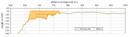
- The screen consists of two parts, each with a different pole dimension; in the first zone the lake bed is between NAP – 0.6 m and – 0.9 m, in the second zone between NAP -0.9 m and – 1.5 m.
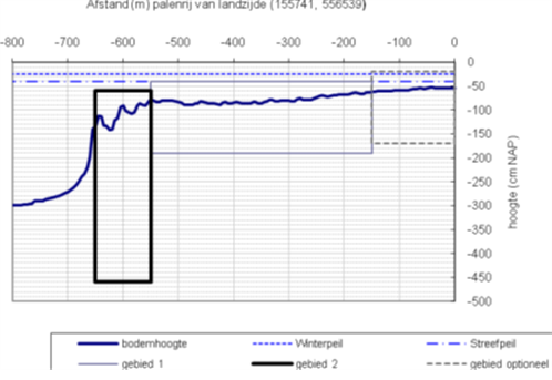
The light blue box indicates the zone between NAP -0.6 and 0.9 m, the black box the zone between NAP -0.9 m and -1.5 m. In Zone 1, between 150 and 550 m from the shoreline, the poles are submerged about 40 cm (below the winter water level). In Zone 2, between 550 and 650 m from the shoreline, the poles have a larger diameter (120 mm) and they are pushed deeper into the bed, in order to withstand the larger wave forces. The pole screen does not extend all the way to the shoreline, but only up to 0.5 m water depth. Trapping sediment at lower depths will have only a limited effect.
| Zone | Distance to shore (m) | Lake bed (m below NAP) | Top of poles (m below NAP) | Pole diameter (mm) | Pole length (m) |
| 1 | 150-550 | -0.4 to -0.8 | -0.4 | 70 | 1.5 |
| 2 | 550-650 | -0.9 to -1.5 | -0.6 | 120 | 4.0 |
Construction of the soft sand machine
Friday March 18th, 2011 marked the official start of the pilot project designing and monitoring the Sand engine Workumerwaard.
First the pole row was constructed. This needed to be done quickly, as the breeding season was about to start. Furthermore, a 4 km long fibre-optical cable was placed in a zigzag pattern at the location where the sand would be deposited. This fibre-optical cable grid is an important innovative means to monitor the actual sand movement and dynamics in the pilot area (more on its functioning below). Subsequently 25.000 m3 of sand was put in place, which turned out to be a challenge. Close to the Workumerwaard the lake IJsselmeer is too shallow for big ships. The sand was transferred to smaller barges and subsequently pumped to the right location. Rainbowing was not allowed, as this would cause too much turbidity.