How to Use
The aim of a perched beach is to create and maintain a dynamic equilibrium profile landward of a submerged breakwater and thereby reduce coastal sediment losses. The design of a perched beach should be based on several considerations, like dimensions and location of the sill or breakwater, the sediment used for the nourishment, the dynamic equilibrium state and the habitat requirements for certain species. The different elements of the design (profile, sill) are interrelated, because the design process is cyclic. The first choice regards the location of the shoreline: should it shift seawards, stay in the same position or is a certain amount of retreat allowed? Depending on this choice, the design of the profile and the sill can be further considered. Below, you can find an overview of the basic theory on equilibrium profiles and perched beaches and some guidance for perched beach design.

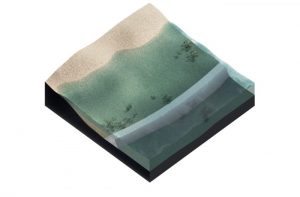
Sketch of perched beach concept with: water depth over the breakwater, d, water depth at seaward and shoreward side of the toe structure, he and hi, respectively, advanced beach width, Δy, and beach berm height, B0
Technical design
Profile

The coastal profile between the breakwater and the coastline is dynamic, but averaged over its variability, it is likely to tend towards an equilibrium shape. This equilibrium profile can be described on the basis of Dean’s theory (1977, 1991), which was later adapted for equilibrium profiles on perched beaches by Gonzalez et al. (1999). The equilibrium beach profile is the underwater profile that is in equilibrium with the ambient wave and current conditions and the characteristics of the sediment.
The equation of the equilibrium beach profile is a power law in the form (e.g. Dean, 1977):
h = A * xm
in which:
h = water depth
A = parameter depending on the sediment characteristics = 0.067w0.44
w = fall velocity
x = distance from the water line
m = slope parameter
Characteristic features of equilibrium beach profiles are:
- Tendency to be concave upwards (m<1)
- Smaller grain sizes result in milder slopes and coarser grains in steeper slopes
- Beach face is approximately planar
- Steep waves result in milder slopes and a tendency to bar formation
The balance between the (wave-induced) forces and the sediment characteristics (important for bottom friction) determines the shape of the beach profile. The slope parameter m can be determined according to the assumption concerning the wave energy dissipation (Dean, 1977):
- Uniform average longshore shear stress: m=0.4
- Uniform average wave energy dissipation by turbulence per unit plan area: m=0.4
- Uniform average wave energy dissipation by turbulence per unit water volume: m=0.67.
This is based on the assumption of spilling breakers: H = 0.8 * h.
Field data were used to verify the analytical solution and to tune the parameters A and m. For this purpose, Dean (1977) compared 502 beaches at the east coast of the United States. This revealed that at this coast the third mechanism is dominant, resulting in a value of 0.67 for the parameter m. He also found that the parameter A depends on the fall velocity of the sediment and derived an empirical relation for the parameter A (see above).
Sill or submerged breakwater
The design of the submerged structure determines the amount of wave energy that passes the structure and arrives at the beach. Gonzalez et al. (1999) argued that submerged breakwaters or sills generally are too narrow to have significant wave energy dissipation by breaking. Also friction-induced attenuation over the structure is negligible, so wave reflection is then the main process determining the amount of wave energy arriving at the beach.
The water depth directly at the landward side of the sill (hi) is a function of the ratio between incoming and reflected wave energy:
hi=he(1-R2)2/5
in which:
he = the water depth at the seaward side of the structure,
R = the reflection coefficient, defined as Hr/He, the reflected wave height divided by the incoming wave height.
The value for R can be derived iteratively and is dependent on the breakwater dimensions (B,d), location of the breakwater (he) and the wave length (L). Subsequently, the water depth at the landward side of the sill can be used to position the equilibrium profile and determine the shoreline advance or retreat, given the grain size of the sediment used for the nourishment. Further derivation can be found in Gonzalez et al. (1999).

Fringing reefs, which are coral reefs along and close to the coast, can protect the coast by dissipating wave energy, rather than reflecting it. Munoz-Perez et al (1999) found that for a natural reef-protected beach to exist, the reef width must exceed three wave lengths. Then wave breaking over the reef occurs, which limits the wave energy reaching the beach. Also friction damping over a wide coral reef can reduce the hydrodynamic energy arriving at the beach. Note that the mildly sloping natural/artificial fringing reefs work in a different way (via wave dissipation) than relatively steep and reflective submerged breakwaters.
Design Parameters
Dimensions and position of the submerged breakwater are important design parameters, because they influence the reflection coefficient and the position of the coastal profile. The grain size of the fill material can be varied to change the profile shape behind the structure. Hence, key design variables are:
- Height and width of the sill
- Water depth / offshore distance at which the sill is placed
- Characteristics of the fill material
- Material used to construct the sill

Lee side erosion/accretion in case of breakwaters of finite length
Ranasinghe and Turner (2006) give an elaboration on the different successes of finite-length submerged breakwater applications. Field observations, model simulations and laboratory test are compared. They conclude that laboratory tests and numerical simulation results imply that shoreline accretion will occur in the lee of the submerged structures located on coastlines with significant ambient longshore sediment transport. In the lee of submerged structures located on coastlines with predominantly shore-normally incident waves, set-up over the structure will cause a water level elevation which induces circulation currents around the heads of the breakwater. The flow pattern closer to the beach as drawn by Ranasinghe and Turner, however, is dubious. As the structure will reflect part of the wave energy, set-up behind the breakwater will be less than that in the fully exposed adjacent zones. Hence there will be a wave-driven current into the sheltered area. Field observations seem to support this, although conclusions can never be definitive, because exclusively normal wave incidence never occurs.

In case the alongshore continuity of the perched beach is a problem, for example because it cannot be constructed between two natural fixed points like rocky outcrops for example, a permeable or submerged groin can be placed at either side of the submerged breakwater to mitigate lee side erosion. This is done at Pellestrina beach, Italy (Lamberti et al. 2005, Raudviki and Dette 2002, Muraca 1982).
Ecosystem services
The main objective of the construction of an underwater sill is to reduce erosion of the beach and thus reduce the volume of fill material needed for the beach nourishment. In addition, a perched beach can stimulate ecosystem development, depending on the design choices made. Fixation of all elements in the physical system by ecosystem engineers has to be prevented, because exchange of sediments between the submerged and dry parts of the beach and dunes must be possible to maintain the beach. When biodiversity is enhanced, the following ecosystem services might be beneficial:
- Stabilizing sediment in the lee of the structure by sea grass meadows;
- Damping of hydrodynamic energy by sea grass meadows, coral reefs, mussel/oyster reefs and mangroves (mangroves only when the structure is emerged);
- Improve water quality by sea grass meadows and mussel/oyster reefs;
- Add recreational value to the area: coral reefs are attractive for snorkeling, diving etc.

Note that all of the ecosystems have specific habitat requirements. This can also have consequences for the perched beach design. For example, when the growth of coral reefs on the submerged structure is desired, the growth of corals is limited to certain water depths in combination with the turbidity (penetration of light). In addition, coral establishment requires hard substrate. This implies that the submerged structure has to be constructed of material suitable for corals, for example riprap. More information on habitat requirements can be found at the Concepts for coral reefs, sea grass, mangroves and shellfish.